WorkTelemetry V2 Sensor Board
Telemetry V2 Sensor Board
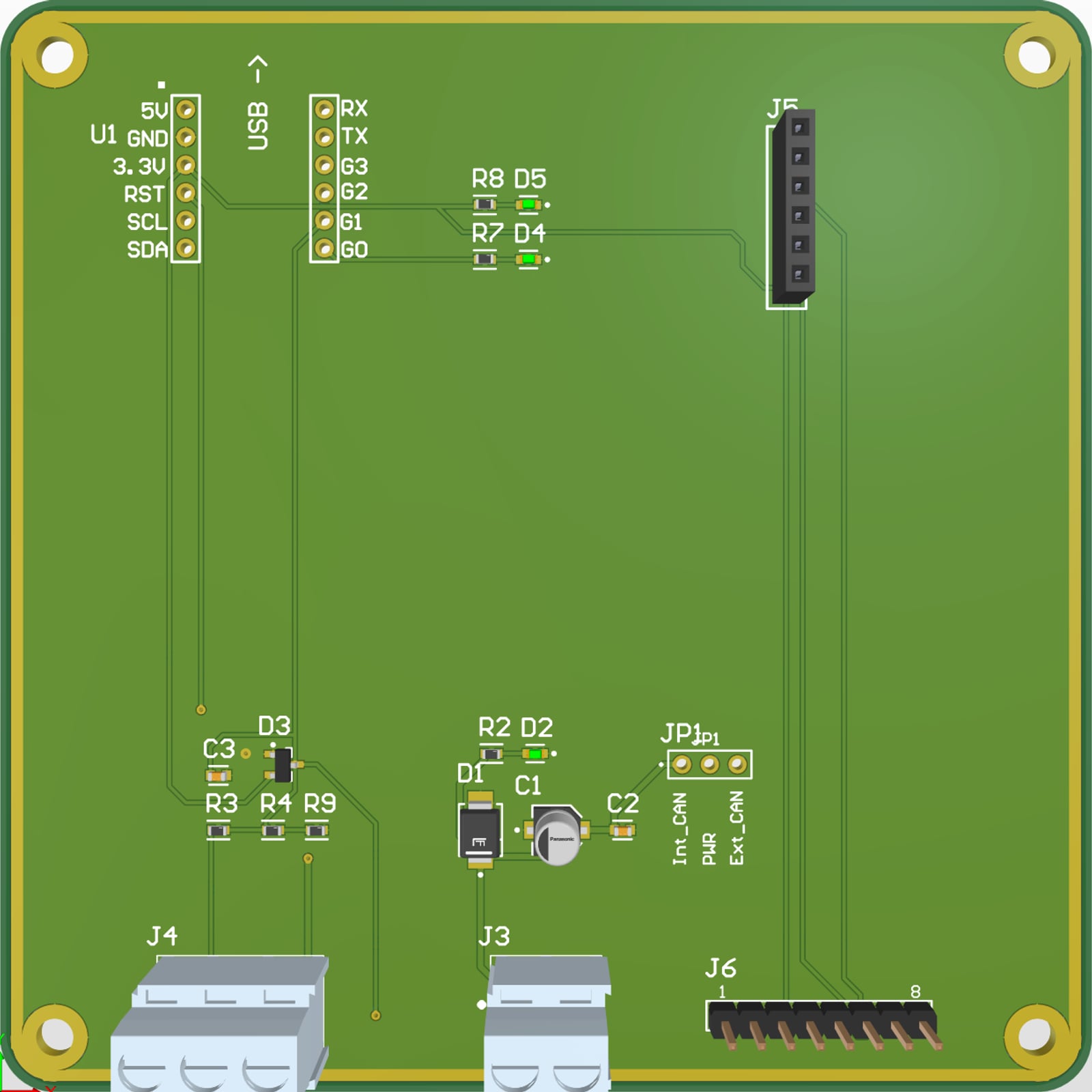
Where it started
uOttawa Supermileage is rebuilding the telemetry on its fuel-efficiency car. The new system, Telemetry V2, puts a small Linux computer in the car and connects the sensors to it over USB. My part is the sensor board, which measures wheel speed and acceleration and sends both to that computer.
The dashboard board was a training exercise for new members. This one is meant for the car, so it had to follow the club's board standard, use parts the club can buy, and be reviewed by the electrical lead before I started the layout.
How it fits in the car
How it came together
- 01
Listing what it connects to
Before drawing anything, I wrote down what the board talks to: the Linux computer on one side, a Littelfuse 55505 Hall sensor and an Adafruit MSA311 accelerometer on the other. That gave me three blocks to design: power, the Hall input, and the USB bridge with the accelerometer.
- 02
Choosing the USB bridge
I used Adafruit's MCP2221A breakout as the bridge. It turns one USB port into I2C and four GPIO pins, so the computer can read the accelerometer over I2C and the Hall signal on a GPIO without any firmware on the board.
- 03
Picking parts
I took every part from Altium's Manufacturer Part Search or the club's library, so each one has a manufacturer part number the club can order.
- 04
Matching the club's schematics
I compared mine with the club's official schematics and copied their conventions: one titled frame per block, net labels instead of long wires, the club's title block, and no notes floating on the sheet.
- 05
Review with the electrical lead
The lead marked up my PDF and I made each change: one electrolytic bulk capacitor, the same ceramic part for all decoupling, a 2.54 mm jumper in place of a zero-ohm resistor, all test points on one 8-pin header, every LED resistor at the same 470 Ω value, and the reset pin brought out to the test header. The electrical rule check ended at 0 errors and 0 warnings.
- 06
The MCP2221A footprint
No footprint existed for the MCP2221A breakout. I pulled the exact pin positions from Adafruit's open PCB files (two rows of six, 2.54 mm pitch, 12.7 mm apart) and wrote them up for the lead, who built the part in the club library.
- 07
Board outline and placement
The outline is the club's 100 × 100 mm board with 5 mm rounded corners and four M3 holes 5 mm from each edge, so it mounts on the car's DIN rail like every other board. I placed the parts by block, in the same arrangement as the schematic, with every connector on one edge.
- 08
Routing
I tried Altium's autorouter first. It routed ground as thin tracks and pulled apart the copper edge ring, so I deleted its tracks and routed the board myself. Power runs at 0.5 mm, signals at 0.3 mm, and both sides are filled with a ground pour. The whole board uses four vias.
- 09
Checking against JLCPCB's rules
The lead had me import JLCPCB's design rules. The first check found 22 errors, all from one cause: part of the copper edge ring had lost its ground net. I fixed it, and the final check shows 0 violations.
What the board does
Wheel speed
A Littelfuse 55505 Hall sensor counts the magnet passing on the wheel. It runs on 5 V, but the MCP2221A reads 3.3 V, so a divider scales the signal down. A 100 nF capacitor filters noise, and a BAT54S diode pair clamps the pin between GND and 3.3 V.
10 kΩ in series, 20 kΩ to ground: 5 V × 20 / 30 = 3.33 VAcceleration
An Adafruit MSA311 three-axis accelerometer plugs into a 6-pin socket and talks over I2C at address 0x62. It runs from the 3.3 V regulator on the MCP2221A breakout, which also holds the I2C pull-up resistors.
I2C at 0x62, powered at 3.3 VUSB link
The MCP2221A breakout connects to the Linux computer over USB. The Hall signal enters on GP1, the only pin that can do both an analog reading and a change-of-state interrupt. GP0 drives a status LED the software can switch on.
GP1: Hall input, GP0: status LEDPower
The car's 5 V comes in through a screw terminal and goes through a 5 V TVS diode, a 10 µF electrolytic capacitor and a 100 nF ceramic. A green LED shows the rail is live.
SMBJ5.0A TVS, 10 µF + 100 nF, 470 Ω on every LEDThe schematic
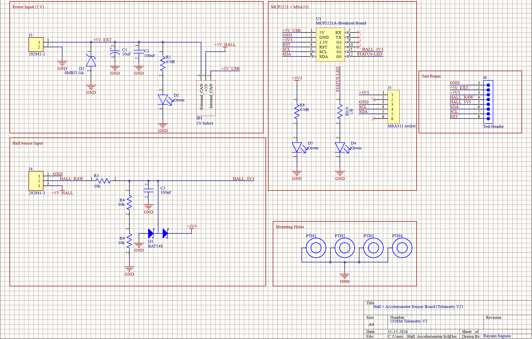
The whole board is on one sheet. Click it to open the PDF.
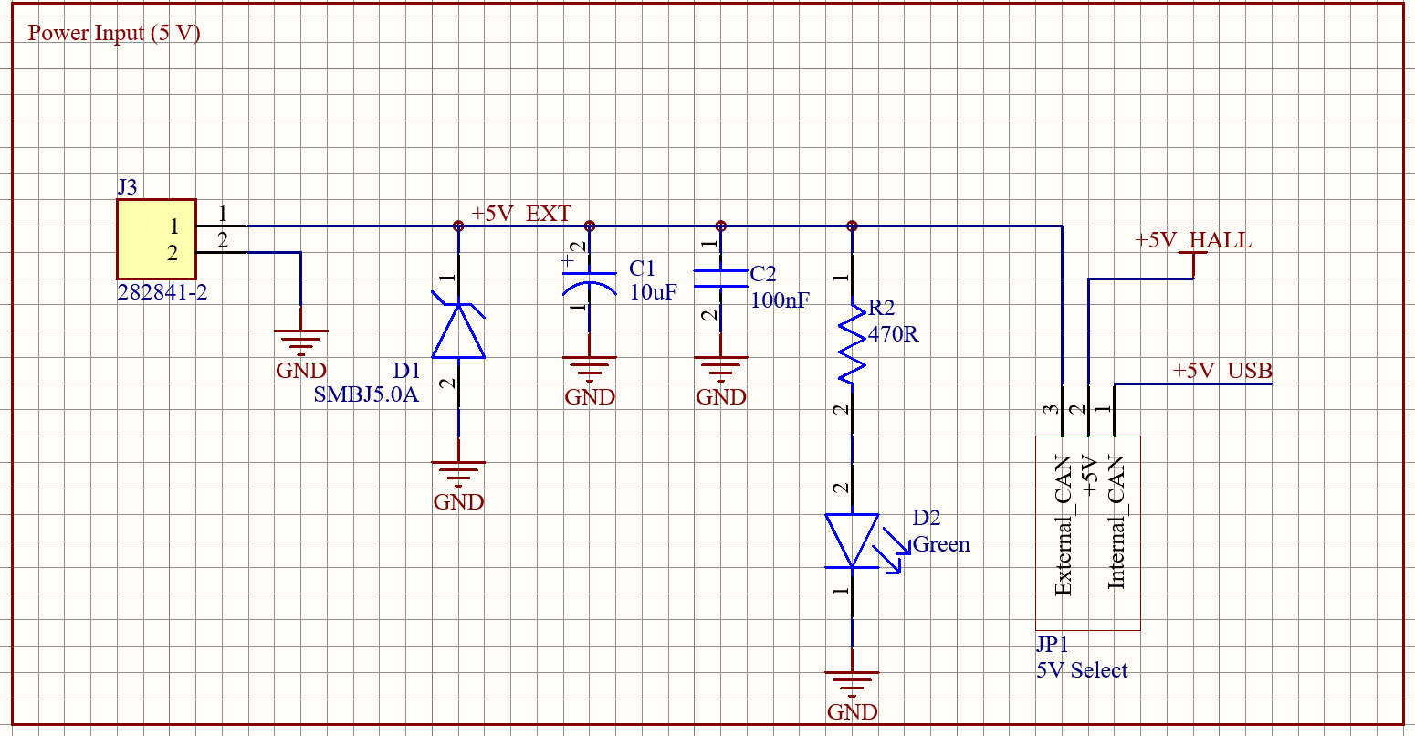
Why there is a jumper (JP1)
The board has two possible 5 V supplies: the car's 5 V and the 5 V from the computer's USB port. The MCP2221A breakout ties its 5 V pin straight to USB power, with no diode. If both supplies met on one net, the car could push current back into the computer's USB port.
I kept them on separate nets and added a 3-pin jumper. Its middle pin powers the Hall sensor, and the cap connects it either to the car's 5 V or to USB 5 V. With the cap on the USB side, I can test the board from a laptop without the car.
The test header
The electrical lead asked for every test point on one 8-pin, 2.54 mm header. To check the board, I can clip a probe on these pins instead of looking for pads.
- 1
GND - 2
+5V_EXT - 3
+3V3 - 4
HALL_RAW - 5
HALL_3V3 - 6
SDA - 7
SCL - 8
RST
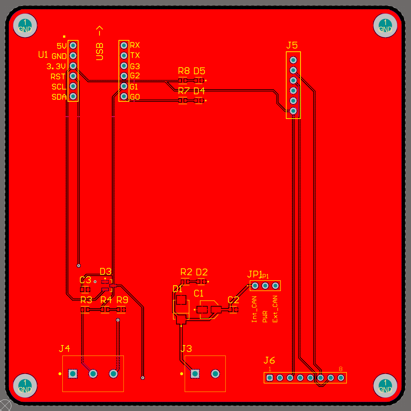
Top and bottom copper
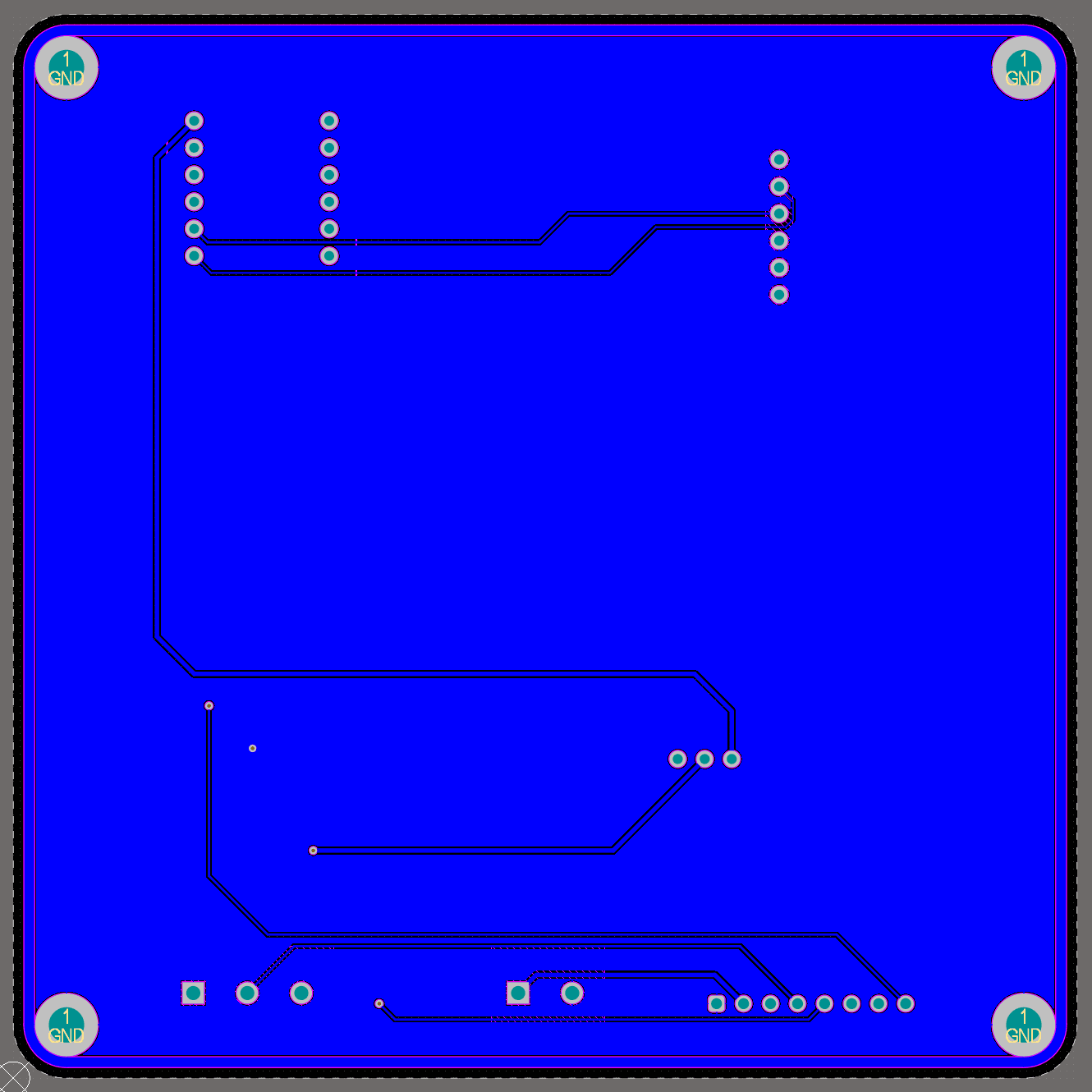
Most tracks are on the top. The bottom has the I2C lines to the accelerometer socket, the USB 5 V going down to the jumper, and the long tracks to the test header.
Specs
- Size
- 100 × 100 mm, 5 mm corner radius
- Layers
- 2
- Parts
- 20 components + 4 M3 mounting holes
- Nets
- 15
- Vias
- 4, 0.4 mm drill
- Track width
- 0.5 mm power, 0.3 mm signals
- Ground
- Poured on both layers
- Edge
- 1 mm exposed copper ring on both sides
- Mounting
- Club standard: 4 × M3, 90 mm pattern, DIN-rail clip
- Checks
- ERC 0 errors, DRC 0 violations against JLCPCB's rules
What it should do
- Car 5 V connected5 V LED on
- USB connected3.3 V LED on, MCP2221A seen by the computer
- I2C scanMSA311 answers at 0x62
- Wheel turnsOne pulse per magnet pass on GP1
- Software commandStatus LED on GP0 turns on
Expected behaviour, not tested yet.
Where it stands
The schematic is reviewed, the layout passes JLCPCB's design rules, and the silkscreen labels every pin and the jumper. Next come the manufacturing files, fabrication, and the first bench test with the Hall sensor and the accelerometer.